Planning and Tender – window joinery design and quotation program
aluplast
More and more often, manufacturers, window dealers, but also architects are faced in conversations, especially with more demanding customers, with the need to present detailed documentation for the windows and doors they offer, including, for example, structural details, cross-sections of the structure, or methods of connecting individual elements. Not all solutions can be presented on a point-of-sale display or artfully and comprehensibly presented in a conversation, hence to enable the requirements of clients to be realized, Aluplast provides free of charge the easy-to-use “Planning and Tender” program, which does not require CAD knowledge. This is a very valuable support in the daily work related to both the design of window structures and their professional presentation. More often than not, it is this kind of comprehensive consulting that presents a chance to win an order.
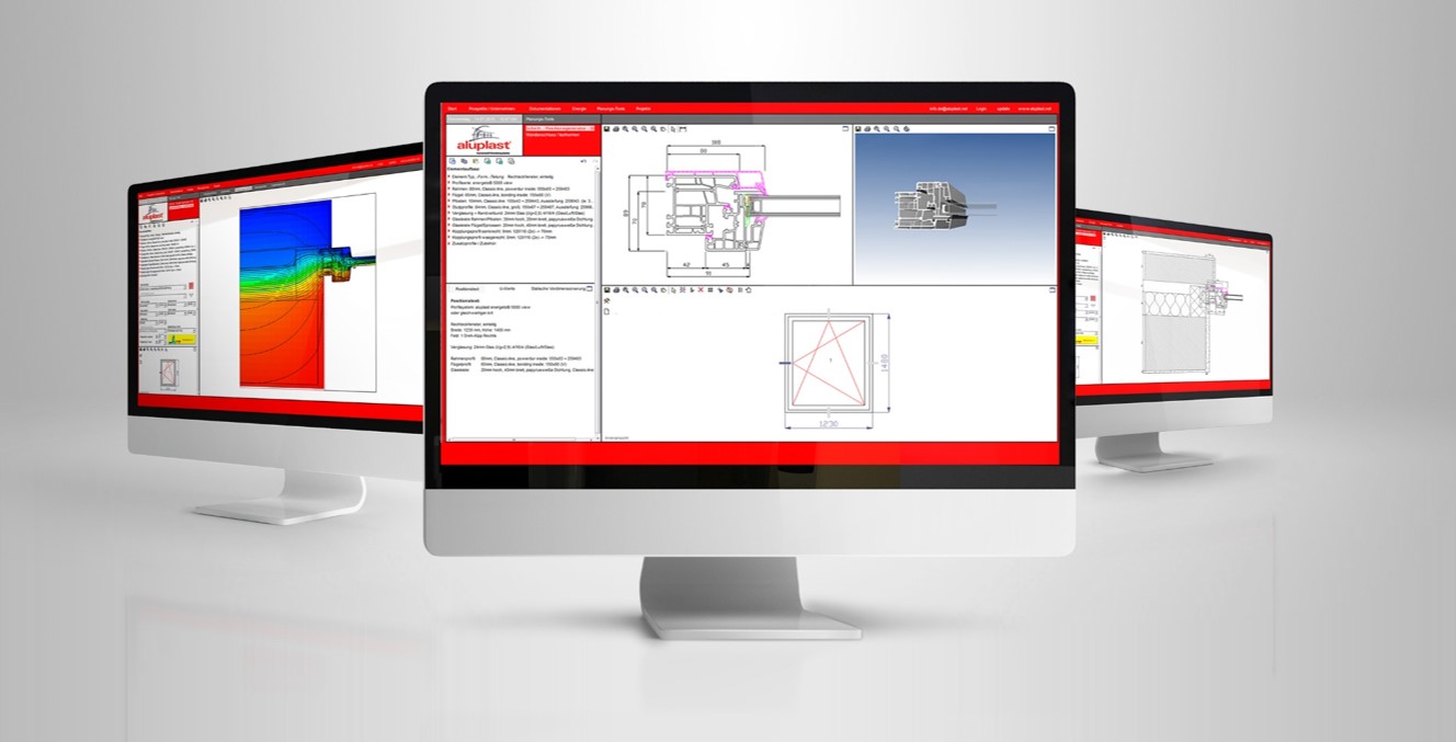
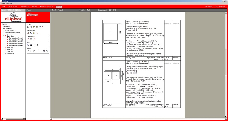
The program contains a number of modules that allow to construct windows and doors, build entire window sets, select additional elements (extensions, connectors, blinds). It is complemented by a three-dimensional presentation of each listing, as well as a detailed report with the created offer. The program also has the ability to calculate the Uw coefficient for the designed structures, create simulations for window installation, and generate isotherm runs for selected solutions. It is also complemented by an “Energy Calculator,” which allows calculating the profitability of replacing window frames and the estimated gains associated with this at given parameters. It is also an up-to-date database of documentation, certificates and technical catalogs, which, thanks to the Internet update function available in the program, will provide you with constant access to up-to-date information. The program is available in several language versions.
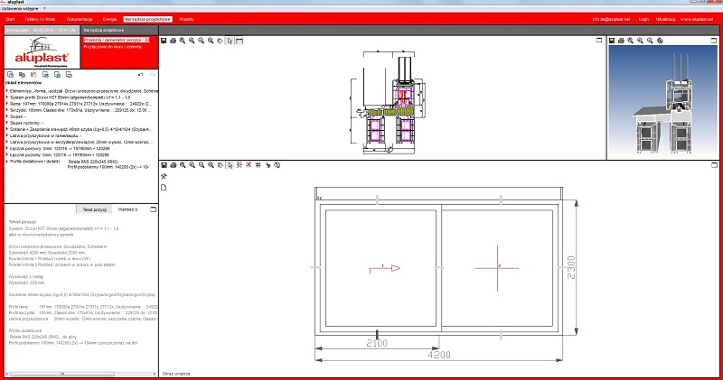
Generation of cross-sections and window elements
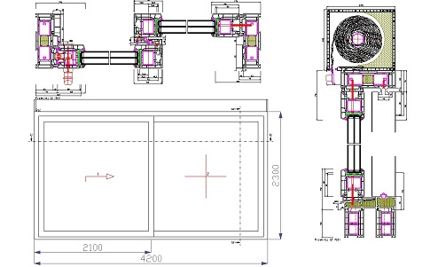
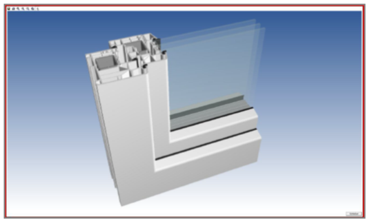
Recently, it has also become increasingly important to provide architects and designers with cross-section drawings of window elements. Often, it is desirable or even required to send relevant CAD data for input into CAD software. The illustration shows an example of an element that can be generated in a few steps. After selecting the type/form/division of the item, the profile series, profiles and glazing are selected. The dimensions of the elements can be changed. You can specify how to open individual lites by clicking the mouse. There are further additional profiles to choose from if needed. The “total cross-section” function allows you to automatically generate a summary of the element with the desired cross-sections at variable scales. The drawing generated in this way can be exported as a graphic or CAD drawing and modified in other programs if necessary.
Create 3D presentations easily
The “3D Section Generator,” which is part of the module that creates cross-sections, is also a very impressive and easy-to-use tool. By selecting a section at the desired location (bottom, center, side or top), the user can view a real-time presentation of the profiles from all sides and rotate them in all directions. In this way, the designed windows can be presented in detail and dispense with taking multiple designs and samples to investors, designers or end customers. This presentation, too, can be exported as a graphic and imported into many popular programs (e.g. Office) to make your offer even more attractive.
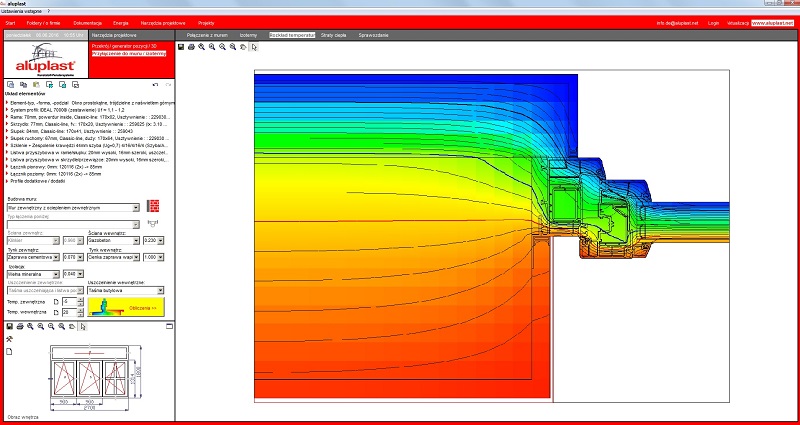
Evaluation and simulation of the assembly situation on the basis of the course of isotherms
The course of isotherms and other conditions are part of the scope of the design, so it is in the design that the location of the window's incorporation and the method of connecting the window to the wall should be specified. These are important issues to later prevent or nullify the formation of negative phenomena in the form of excessive condensation. Graphical presentation of isotherms at a typical window-wall junction makes it possible to assess whether dew will form on the glazing under normal conditions. Graphics showing the course of isotherms, heat flow fluxes and information on selected building elements will help with detail design. This makes it quick and easy to check the correct installation location before installing the windows, so that the designer and contractor can make sure that there will be no condensation on the surfaces.
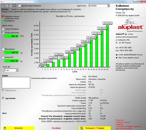
Energy Savings Calculator
The “Energy Savings Calculator” program provides a diagram form and numerical summaries of the potential cost and energy savings of replacing old windows with new ones, while it is possible to include air conditioning or heating or both. In addition to the stored standard values and standard selection lists (drop-down lists), the program also provides the ability to modify all values and thus allows you to perform detailed and individual calculations according to your wishes and expertise. The “Results” tab presents detailed data and diagrams indicating potential cost and energy or emission savings over various time periods. The whole is compiled into a report and can be saved as an RTF document (e.g. for Microsoft Word) and/or printed. Such a report is a good argument when making an offer to convince the customer to install new windows with better parameters.
More and more people are aware that their knowledge and competencies can significantly contribute to competitive advantage. Certainly, the “Planning and Tender” program is another tool for highlighting your offers and creating original presentations.
To access the “Planning and Tender” program, complete the registration form at https://plan.aluplast.net/